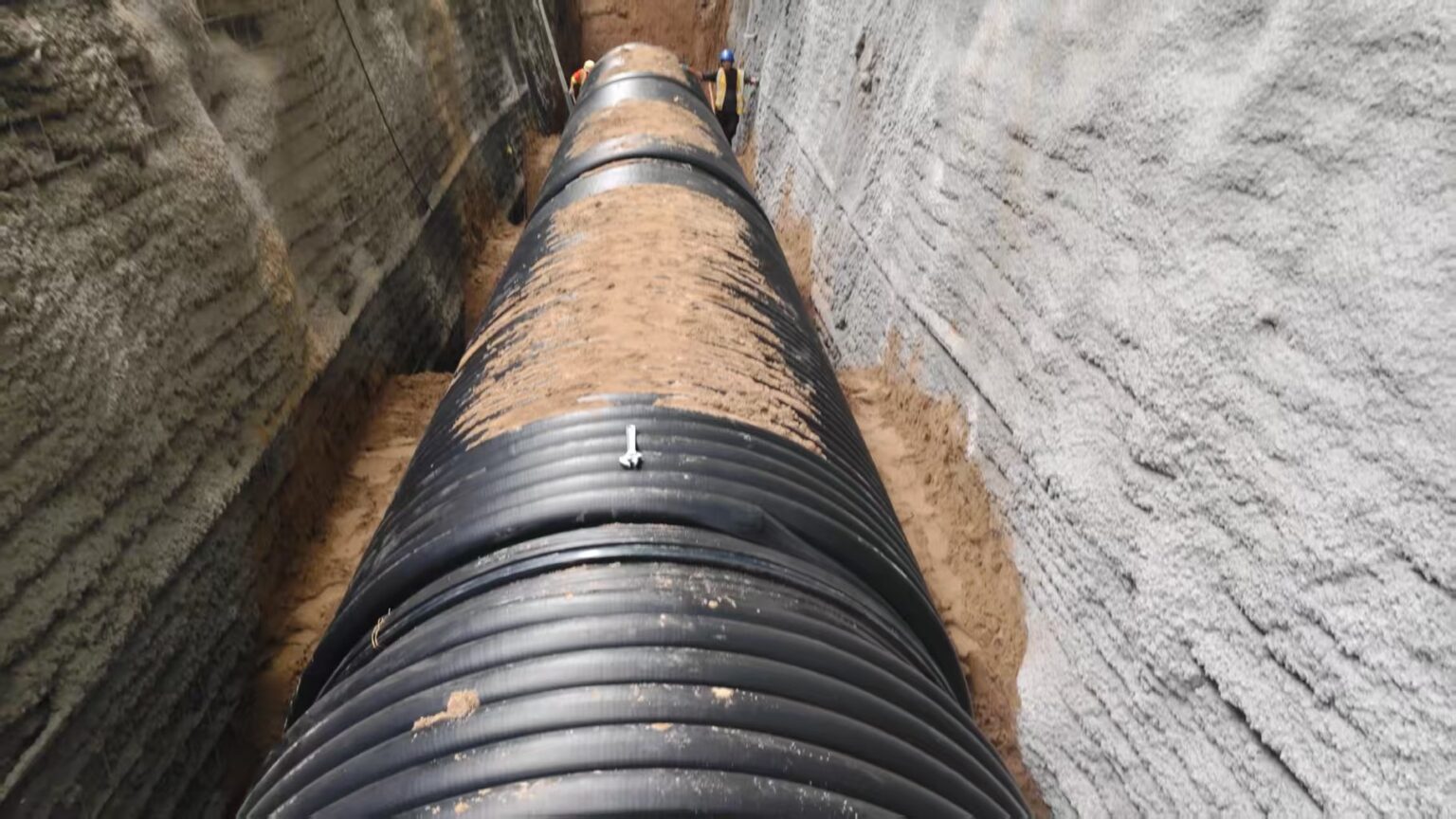
Conduction Area
During trench construction and pipe installation, appropriate measures must be taken to prevent soil, debris, or other foreign materials from entering the conduction area (12). At the same time, the movement of bedding or embedding material from the conduction area into the surrounding soil must be avoided.
The conduction area must remain stable throughout the installation process and should be protected against any foreseeable changes that could negatively affect its load-bearing capacity, stability, geometry, or position.
Potential causes of deterioration may include:
- Removal or collapse of the trench side walls;
- Infiltration or influence of groundwater;
- Excavation or other construction activities in adjacent areas;
- Movement of surrounding soil or excessive external loading.
The trench should be inspected regularly during construction, particularly after heavy rainfall or groundwater changes, to ensure that the conduction area remains stable and suitable for pipe installation.
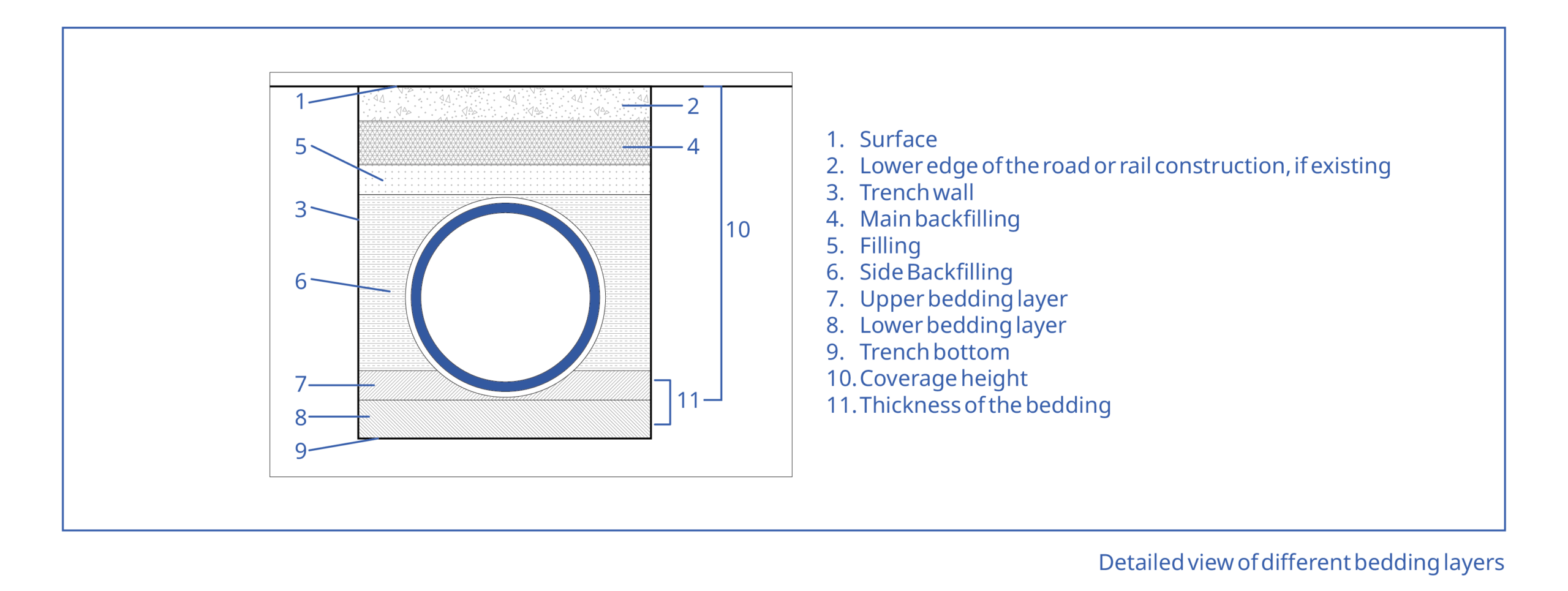
Water Retention and Dewatering
During pipe installation, the trench must be maintained in a stable and adequately drained condition and kept free from standing water.
The selected dewatering method must not disturb the bedding, conduction area, surrounding soil, or installed pipeline. Pumping or drainage operations should be carefully controlled to prevent soil erosion, piping, settlement, or movement of the pipe.
Where groundwater is present, suitable drainage or groundwater control measures should be implemented before and during installation. Further requirements and recommendations regarding trench conditions and groundwater control should be followed in accordance with EN 1610.
Trench Width
For pipes installed using the electro-fusion socket jointing technique, large access openings or additional trench width specifically for welders are generally not required.
The trench width specified in EN 1610 or determined by the relevant structural/static calculation is normally sufficient. However, sufficient working clearance must always be provided to ensure that the electro-fusion welding equipment can be positioned and operated safely and without obstruction.
The trench should also provide adequate space for proper pipe alignment, bedding installation, compaction, inspection, and safe access for workers.
Compaction of the Conduction Area
The quality of the pipe embedding and surrounding soil has a significant influence on load distribution, pressure distribution, and the long-term deformation behavior of the pipeline.
Improper or insufficient compaction may result in excessive pipe deformation, reduced structural performance, or uneven loading. For this reason, the bedding and side-fill material must be installed and compacted carefully according to the project design and applicable standards.
For pipes with a diameter of DN/ID ≥ 1000 mm, it is recommended that the pendentive area beneath and alongside the pipe be compacted using suitable compaction equipment.
For pipes with a diameter of DN/ID ≤ 900 mm, the lateral compaction effect generated by the selected equipment is generally sufficient to achieve adequate compaction in the pendentive area, provided that the appropriate equipment and procedures are used.
The pendentive area has to be compacted as follows:
• The side of the pipe has to be compacted with a respective vibratory plate.
• In the range of the pipe area (figure 1, pipe support and embedding, up to 0.30m under the pipe crown, if embankment sideways of the pipe at least 1,5 x da, only the compaction soil which is indicated in ATV Standard A127 may be used.
The bedding material has to be filled up in layers of 30 cm maximum. The soil on both sides of the pipeline has to be filled up in layers at the same time and compacted accurately. It has to be paid attention that the pipeline remains in its position. The compaction grade Dpr has to correspond to the indications in the static calculations of ATV A 127.
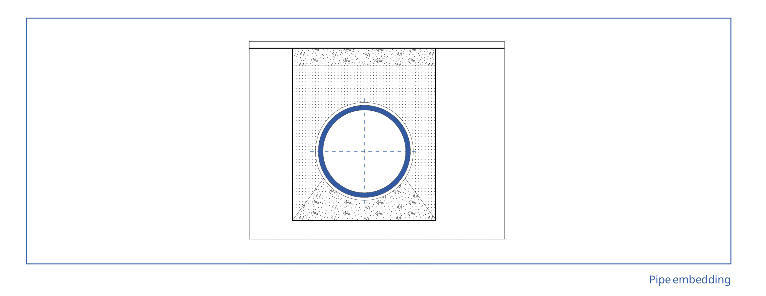
The EN 1610 describes the following three types of carrying out the bedding:
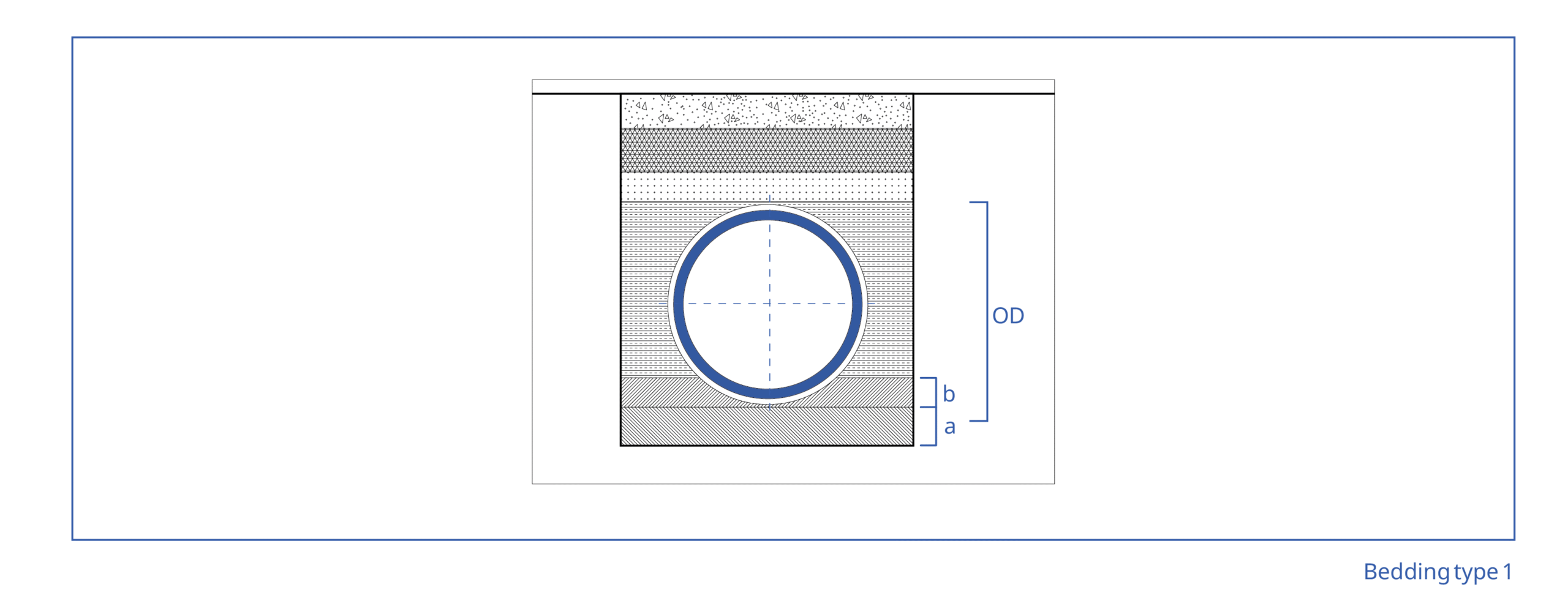
Bedding type 1 (figure 2) can be used for any conduction area, that allows a support of the pipes along their total length and that is produced by taking the required thickness of layers (a) and (b) into account. This applies for any dimension and form of the pipes. As far as nothing else is given, the thickness of the lower bedding layer (a) measured under the pipe bottom should not be lower than the following values: • 100 mm with normal soil conditions • 150 mm with rock or hard soil
Bedding type 2 (figure 3) may be used in smooth, relatively loose, fine-grained soil, which allows a support of the pipes in their total length. The pipes can be laid directly on the pre-formed trench bottom. The thickness (b) of the upper bedding layer has to be according to the static calculations.
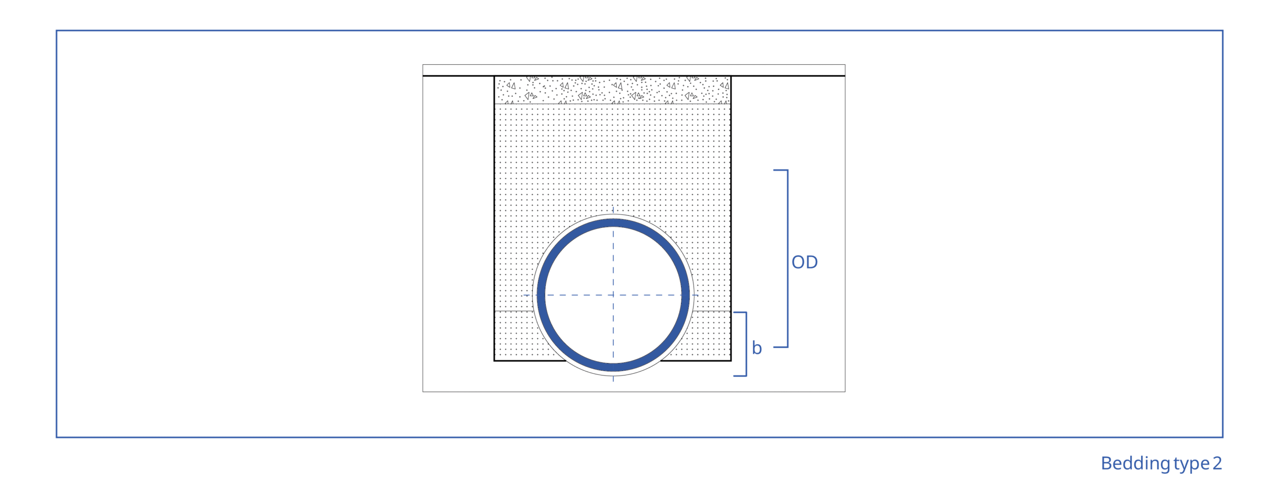
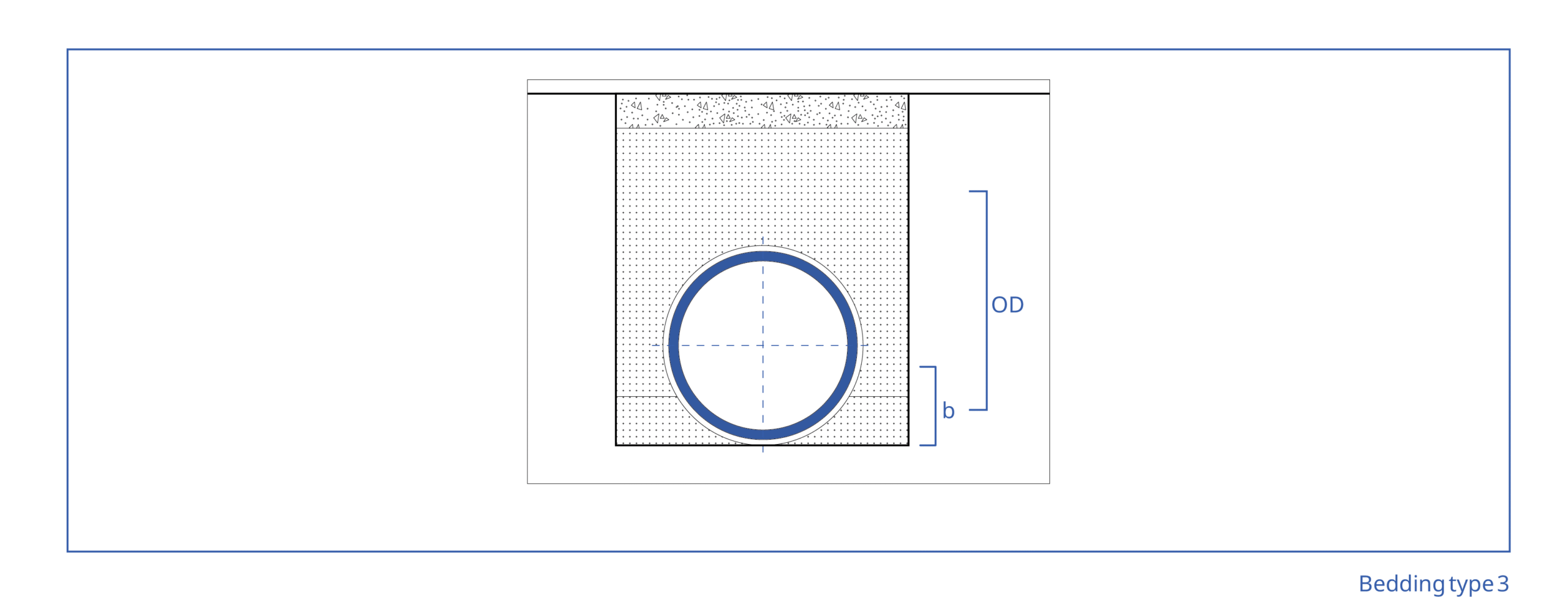
Bedding type 3 (figure 4) may be used in smooth, relatively loose, fine-grained soil, which allows a support of the pipes in their total length. The pipes can be laid directly on the pre-formed trench bottom. The thickness (b) of the upper bedding layer has to be according to the static calculations. Decisive is the bedding type which is indicated in the static ATV A 127!
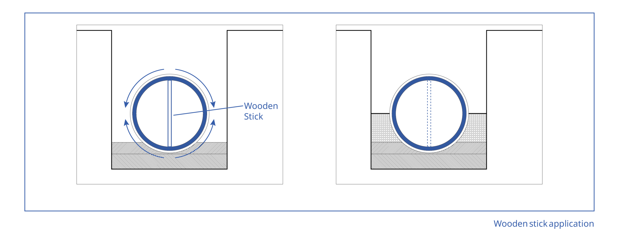
Pipes and components change their dimensions under big variations of temperature. If you try to join two pipes with two different temperatures you may get problems with the tolerances of the joints. Store the pipes under the same outside conditions or take care that you store a new pipe for at least 30 min. in the trench before jointing. For the compaction works the below shown simplification has been proved in practice, which gives first information of a compaction on the side of the pipe.
Before the compaction works with suitable devices, a wooden stick, which is adapted in its length to the inside pipe diameter, can be put vertically into the pipe. After compaction on the side of the pipe, the pipe becomes a little bit vertically oval, but which is hardly measurable. The clamp effect for the wooden stick decreases and it drops.
The compaction grade required according to the static calculation has to be checked by a device-specific regulation or has to be proved by a measurement. The load which is determined in the static requires that in the trench filling the compaction grade is proved.